Structural
Statically inteterminate reaction force analysis VM001
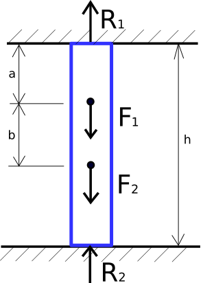
An assembly of three cylinder bars is supported at both end surfaces. Forces \(F_{1}\) and \(F_{2}\) is applied on the middle of the assembly as shown in Figure [fig:ch5_vm_001_schematic].

The input data about material, geometry, and loads are given in Table [tab:ch5_vm_001_parameters].
| Material Properties | Geometric Properties | Boundary Conditions |
|---|---|---|
| Young's Modulus E=2e11 | h=10 | \(F_{1}\)=2000 |
| Mass Density \(\rho\)=7850 | a=3 | \(F_{2}\)=1000 |
| Poission's Ratio v=0.3 | b=3 |
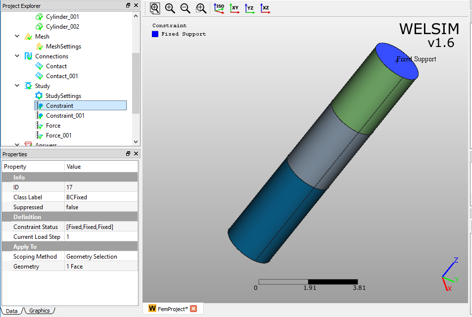
The geometries and imposed boundary conditions are shown in Figure [fig:ch5_vm_001_bc].
The result comparison is given in Table [tab:ch5_vm_001_result].
| Results | Theory | WELSIM | Error (%) |
|---|---|---|---|
| Z Reaction Force at Top Fixed Support | 1800 | 1810 | 0.556 |
| Z Reaction Force at Bottom Fixed Support | 1200 | 1202 | 0.167 |
This test case project file is located at [vm/VM_WELSIM_001.wsdb].
Rectangular plate with circular hole subjected to tensile pressure VM002
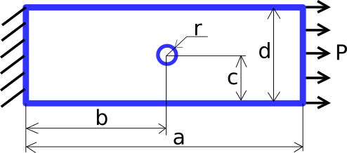
A rectangular plate with a circular hole is fixed along one of the end faces. A tensile pressure load is imposed on another end face as shown in Figure [fig:ch5_vm_002_schematic].

The input data about material, geometry, and loads are given in Table [tab:ch5_vm_002_parameters].
| Material Properties | Geometric Properties | Boundary Conditions |
|---|---|---|
| Young's Modulus E=2e11 | a=15 | Pressure P=1e4 |
| Poission's Ratio v=0.3 | b=7.5 | |
| c=2.5 | ||
| d=5 | ||
| thickness=1 |
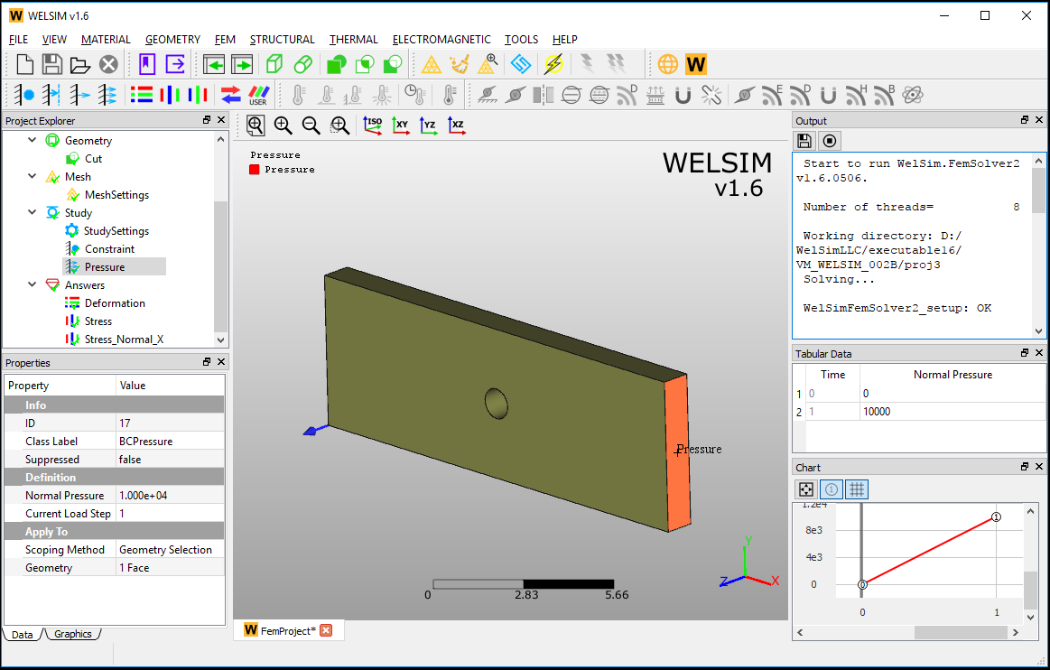
The geometries and imposed boundary conditions are shown in Figure [fig:ch5_vm_002_bc].
The result comparison is given in Table [tab:ch5_vm_002_result].
| Results | Theory | WELSIM | Error (%) |
|---|---|---|---|
| Maximum Normal X Stress | 3.125e4 | 3.156e4 | 0.992 |
This test case project file is located at %Installation Directory%/vm/VM_WELSIM_002.wsdb.

